How to create a moving dots material
16 min read
This is a technical post that focuses on the implementation of one of the materialshttps://dev.epicgames.com/documentation/unreal-engine/unreal-engine-materials we use in level one of AGENCY. It is a material that contains a combination of static and moving dots:
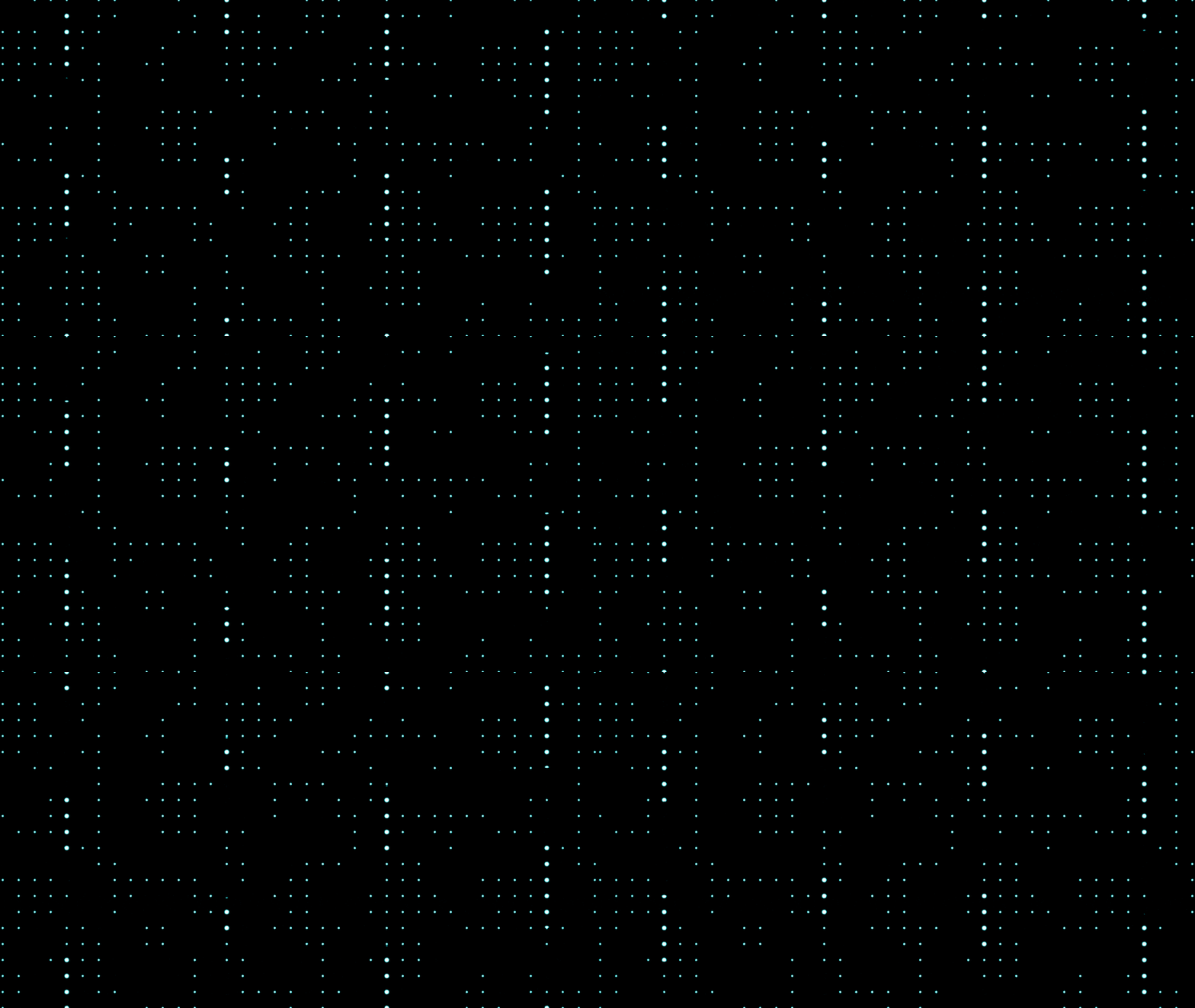
If you have checked out the About page above, you already know that we are a small indie team of two. And neither one of us is an artist! For those reasons, we worked hard on an aesthetic that is visually appealing and unique, while making it easy for us to implement. When learning about materials, we relied heavily on Unreal Engine’s three part UI Material Lab tutorial series. Here are the links to the three parts:
Even though the tutorials are about making materials for UI elements, we found that we can adapt and use a lot of the teachings from the course to achieve our desired aesthetic, an abstract, minimalist look. In this post, I show how I do this by going over the dots material presented in the gif above.
Creating evenly spaced dots
The first step is to create a set of evenly spaced dots in a square pattern, to get something that looks like this:
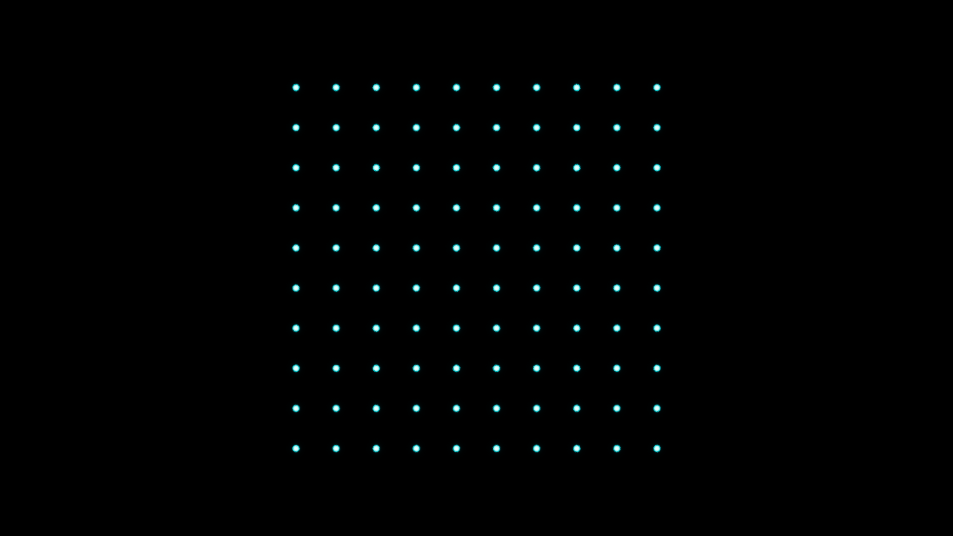
To create this, we need to decide the number of dots in each dimension. I call
this DotDensity. In the picture above, DotDensity is 10 (since there is a
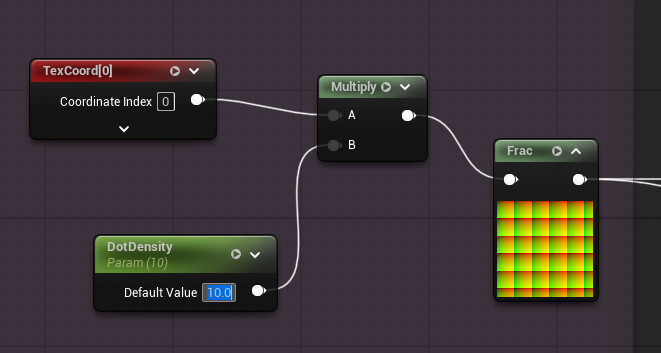
10 x 10 square of dots). In the material, I multiply the input UVs by
DotDensity and remove the integer part, so that the UV range 0.0 - 1.0 is
repeated DotDensity times in both the x and y directions.
Next, I plug the multiplied UVs into the material function MF_UI_SDF_Circle. This function can be used to draw a filled circle:
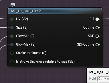
If the input size to the MF_UI_SDF_Circle function is constant and
DotDensity is set to 10 (or any other number you prefer), you will get a
square area of dots:
Varying dot size using a mask
I added some variation to the size of the dots in the material so that they look more interesting and less uniform:
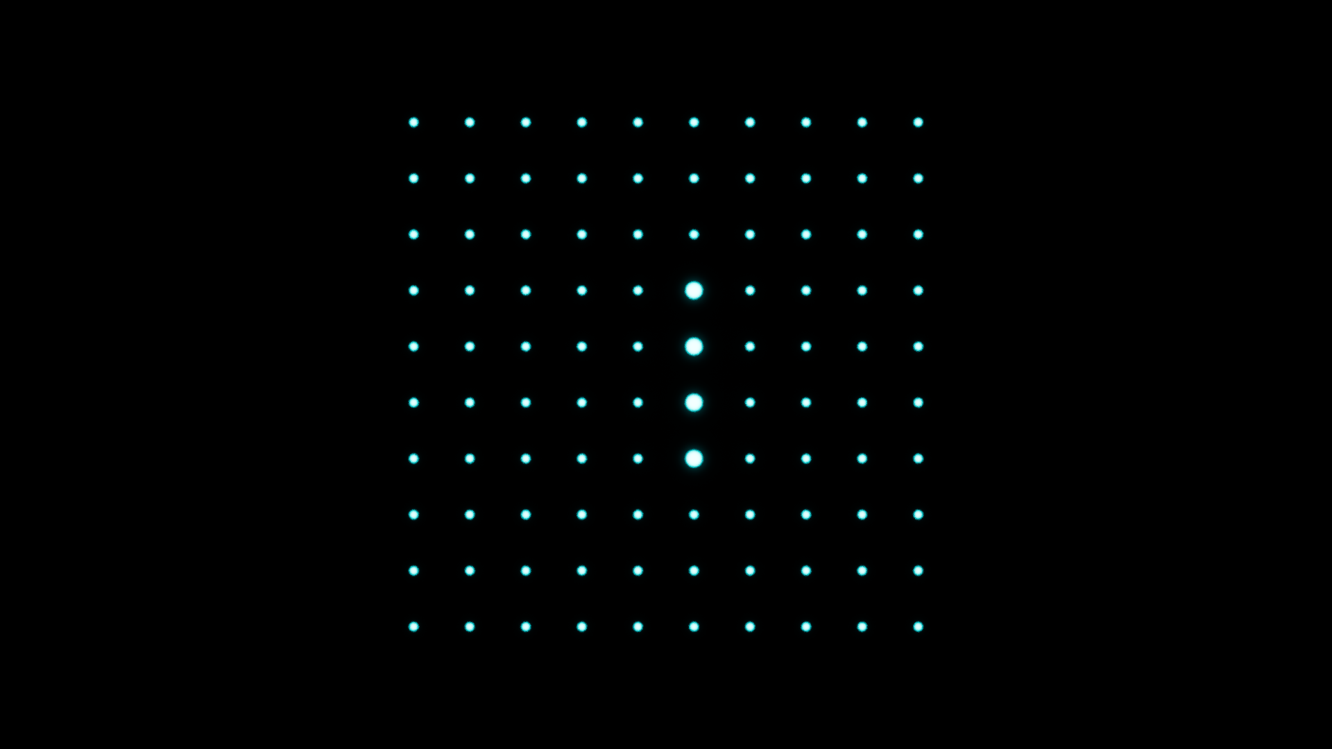
As you can see, some of the dots are larger than the rest. To achieve this variation, we need to create a mask that selects an area in the tile such that dots in that area have a different size compared to the dots outside of the area. The mask looks something like this:
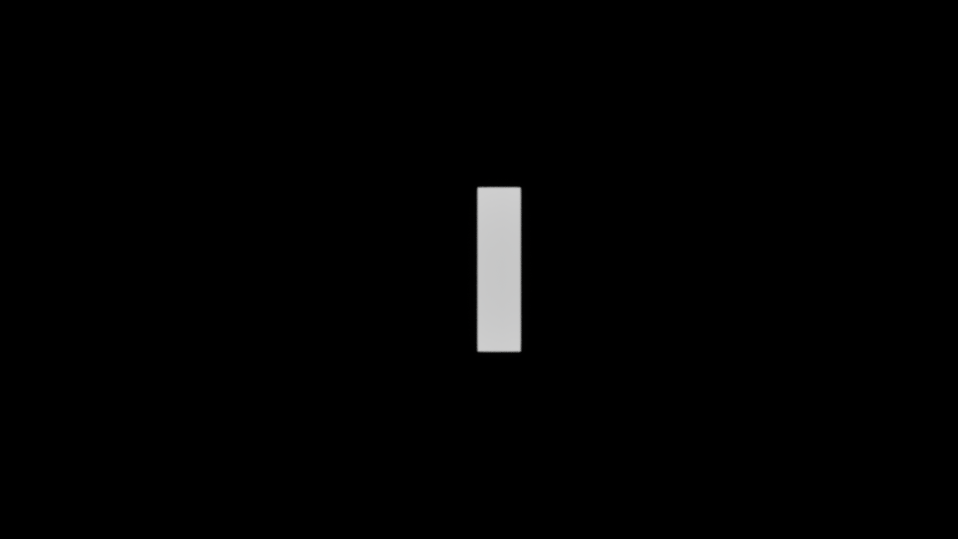
This is created using a slightly modified version of the function
MF_UI_SDF_Box.
By default, this function is meant to be used within a UI element. It has static
bool input parameter Keep Aspect Ratio whose default value is true in the
original function. I decided to create a copy of the function and set the
default value to false here. I could have just input the false value through
the parameter, but since we are using this function a lot for non-UI materials,
I made a version that works in that setting by default.
The following snippet shows how the mask is calculated. The width of the white
rectangle is based on DotDensity because it needs to be wide enough to cover a
single dot. As for the length, you may set it to a constant value. As I explain
further below, I chose to vary it to get some nice effects.
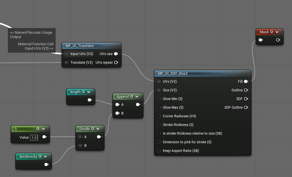
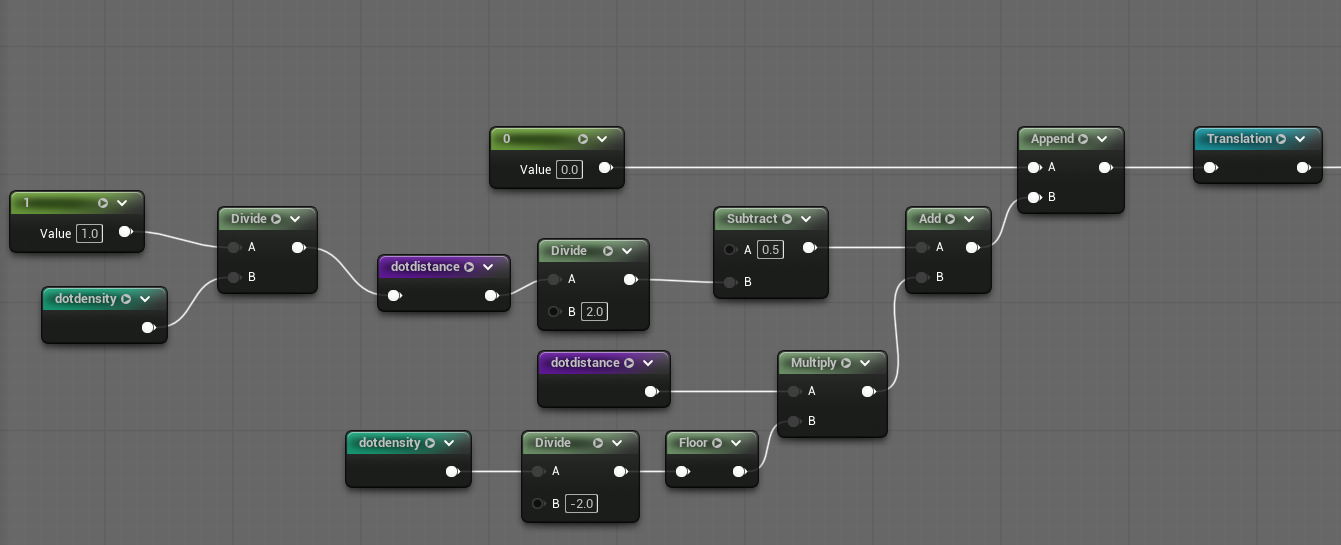
The UVs fed to the MF_UI_SDF_Box function are also translated in a way that
leaves the white rectangle close to the middle of the tile, but also centered on
one of the dots across its width.
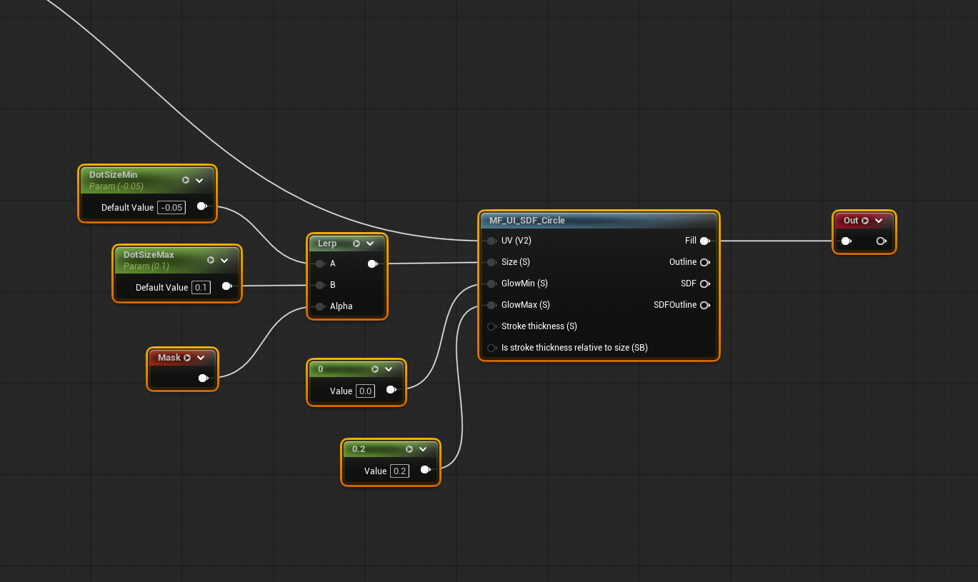
The Mask is used to choose between two possible sizes for the dots using a
lerp node. The output of the lerp is connected to the size input of the
MF_UI_SDF_Circle function:
And this is what we get now:
I would like to note that in our material, I actually use
MF_UI_Halftone,
a powerful function that offers several different features. I use it to repeat
dots in a square tile and to vary the size of the dots. In the previous section
and this one, I explain how to do repeating and size variance from first
principles because I think it is good to know and understand the basics. If I
had just shown my use of the MF_UI_Halftone function, it would have been more
confusing.
Moving the mask
The next thing I do is move the line of larger dots, so that the material has more life to it:
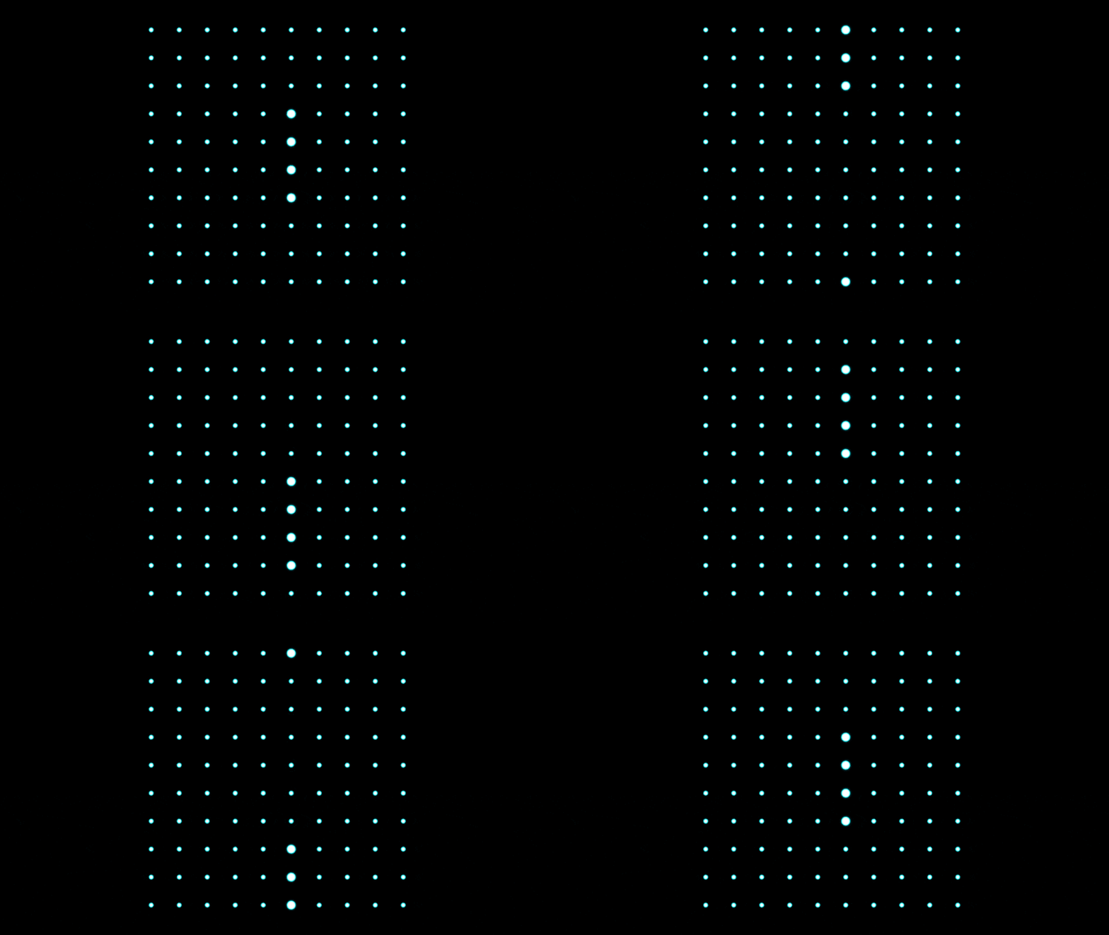
This effect is achieved by making the mask in the previous section dynamic by feeding it “moving UVs.” The following snippet of our material shows how I move the UVs:
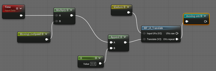
The UV coordinate in the direction of the movement of the dots is translated
using the output of the Time node multiplied by the line movement speedNote
that in the screenshot, I am translating tileduvs to get the moving UVs. These
tileduvs are used to get the final complex material and are explained in
further detail below.. The translation is achieved using another function from
UI Material Lab,
MF_UI_Translate.
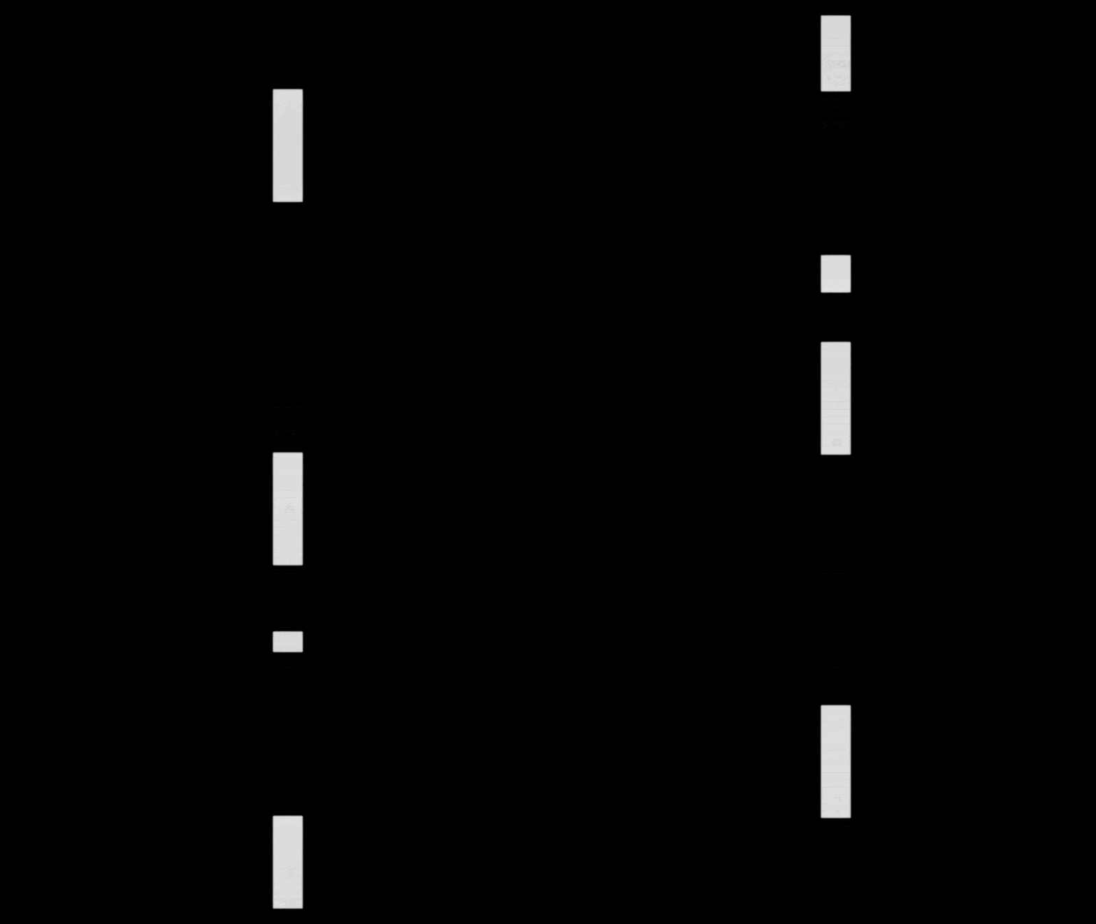
This is what the moving mask looks like when you plug the moving UVs into the
MF_UI_SDF_Box function:
Recall that we applied the static mask earlier by feeding it into the size
input of the MF_UI_SDF_Circle function. If you use this moving mask instead of
the static mask, you will get a square tile with a line of moving dots:
Later, I will show how to vary the speed and the offset between different lines.
Repeating the base tile with the moving dots
Now that we have a material with a single moving tile, we can expand it to make a material with multiple tiles and moving lines:
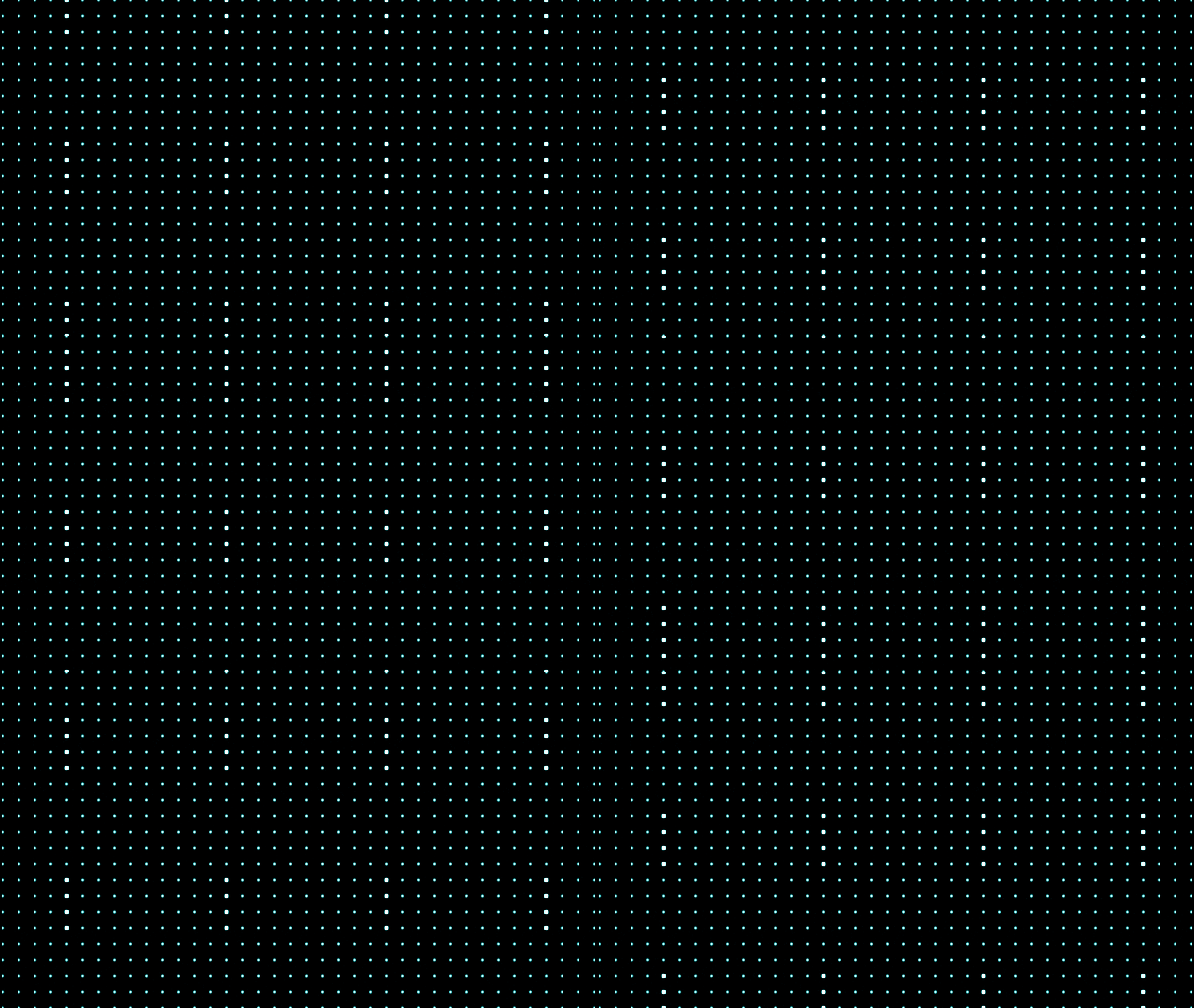
This is done using basically the same technique we used to get the single tile
in the first place. I use
MF_UI_GridTiling
to get an initial set of tiled UVs that have a dimension of DimX x DimY.
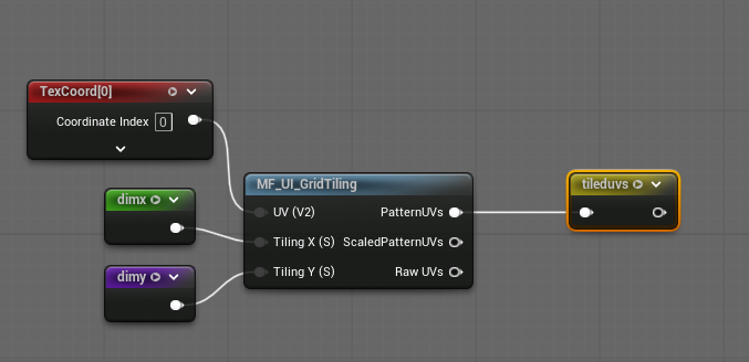
These are then multiplied by DotDensity followed by a frac (as shown in the
“Creating evenly spaced dots” section above):
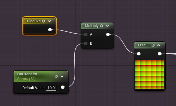
This way, we get two layers of tiling. The outer layer, obtained using
MF_UI_GridTiling, returns the UVs to use when we want to repeat some pattern.
The inner layer, obtained by multiplying by DotDensity, gives us the 10 x 10
tile of dots that will be repeated in the outer layerIf you open the
implementation of MF_UI_GridTiling, you will notice that what it does is
functionally similar to what we do when we multiply by DotDensity followed by
frac. The difference between the two is that MF_UI_GridTiling provides some
additional functionality related to UI elements and aspect ratios..
In the following sections, I explain how I create variations along different tile columns.
Varying line start
We want the moving lines to have offsets amongst each other:
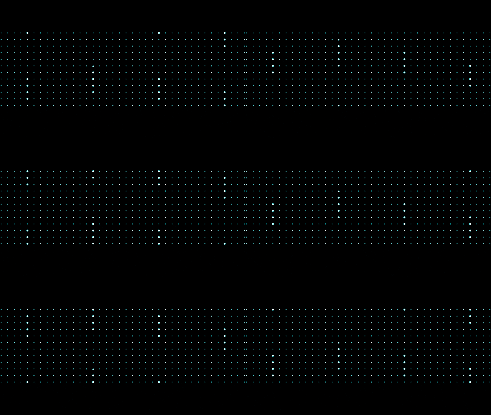
The unevenness makes the material more interesting. For this, I use the
MF_UI_TimeDisplace
function. This function applies a delay to an animation based on something
called a delay mask. The link to MF_UI_TimeDisplace explains the concept in
greater depth.
Recall that we created moving UVs earlier using the Time node, which we then
plugged into the MF_SDF_UI_Box function to create a single moving mask. We are
going to change how we make those moving UVs by using MF_UI_TimeDisplace:
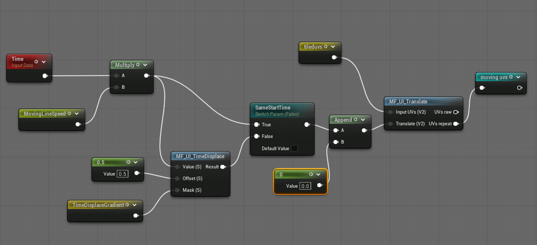
After multiplying the Time node by the speed, I feed it to the value input
of MF_UI_TimeDisplaceThe Offset input should be a scalar and as documented
in the link to the function, “values above 1 could give unexpected results.”
Based on my understanding, I think the Offset should be understood as the
maximum delay but don’t quote me on this! The real variability in delay is
introduced using the delay mask.. The delay mask, which I refer to as
TimeDisplaceGradient, is computed as follows:
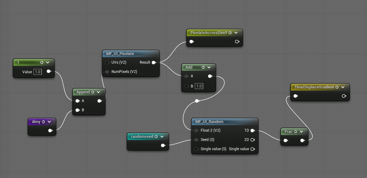
What I want is simple: each column of tiles should contain a single random number, which should then be used as a delay within those column of tiles.
However, as you know, materials perform the same calculation independently for
each pixel. This means we need to ensure that all the pixels that belong to the
same column of tiles end up computing the same random number. This is where I
use the material function
MF_UI_Pixelate.
With this function, we can place the pixel being computed into one of 1 x DimY
buckets. Each bucket is identified using a unique 2D vector returned by
MF_UI_Pixelate. This 2D vector is then fed into
MF_UI_Random
to create a random number for that bucket. This gives us the single random
number per column of tiles.
You will have noted that I do a 1 + to the output of MF_UI_Pixelate. This is
to avoid zero values as inputs to the random function. When the input is 0, the
1D output of this particular random function is 1, which if you then feed to
frac, is 0. I just wanted to avoid this scenario and did a 1 +This is also
a habit I’ve picked up when working with this particular random function. In a
previous material from eons ago, a zero input to the random function broke the
material in a way I cannot remember. However, I remember being upset that the
material broke so the trauma lives on and I do a 1 +. I refuse to remove it
here but you may if you wish to. Let me know what happens if you do..
With the use of MF_UI_TimeDisplace combined with the mask from earlier, we now
have a tiled material where the lines of dots are offset with respect to each
other, while still moving at the same speed:
Varying line length
The next variation is to tweak the length of the lines of dots across the different columns of tiles, to get something that looks like this:
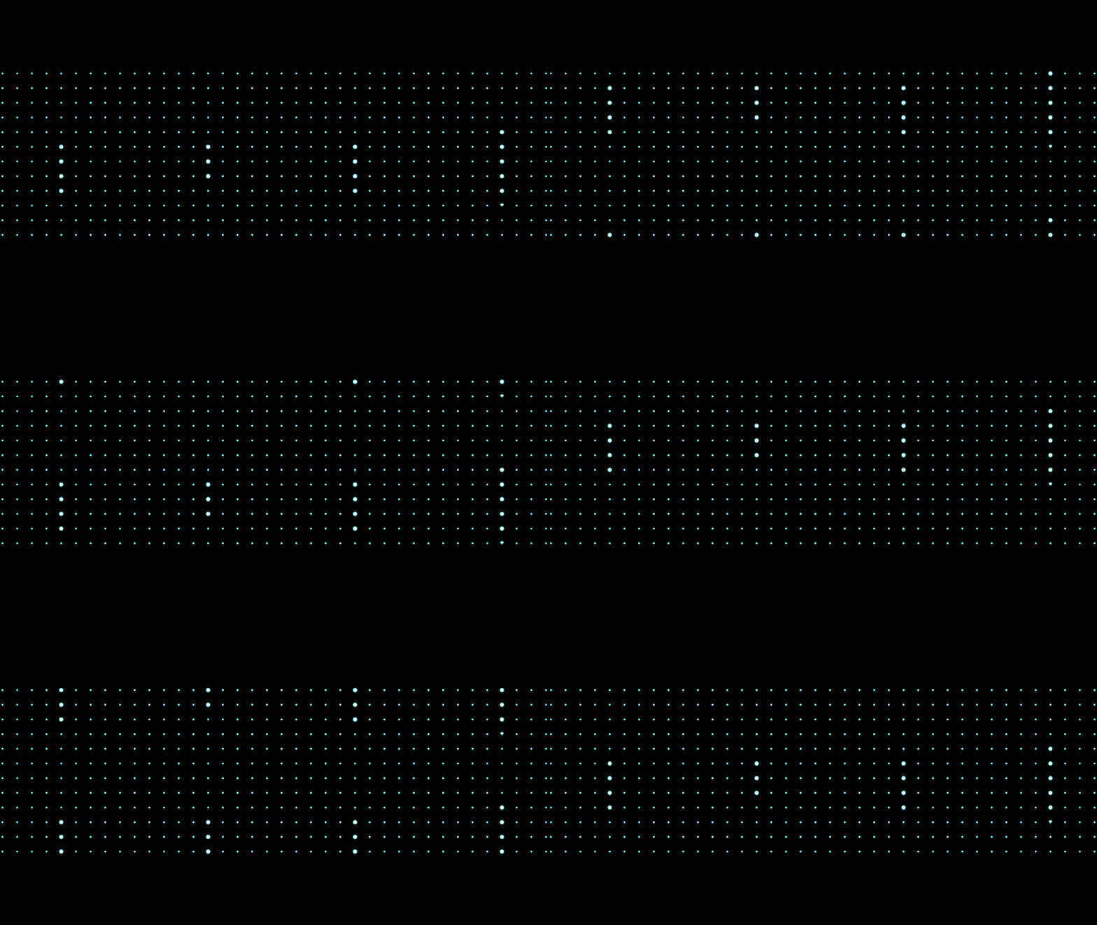
In the section “Varying dot size using a mask”, we see that there is a reroute
node called length that determines the length of the mask. By calculating a
different box mask length for each material column, we can vary the number of
dots that move in each column. This is how that length reroute node is
calculated:
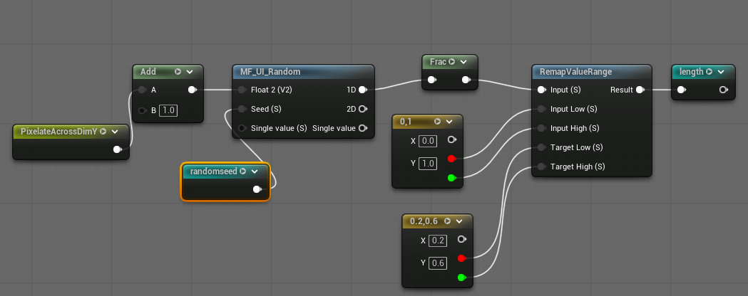
In the earlier use of MF_UI_Pixelate, I sent the output to a reroute node
named PixelateAcrossDimY. I use that reroute node here to calculate a
different random number for each column. By using the frac and the
RemapValueRange nodes, I ensure that this random number is within the range
0.2 - 0.6. This random number is then used as the length to generate the box
mask. I am satisfied with how this looks but if you wish, you may make the range
an input parameter, so that you can vary it to something else (e.g.:
0.1 - 0.9).
Varying line moving speed
Yet another variation is to change the speed at which the lines in the different columns of tiles move, to get something that looks like this:
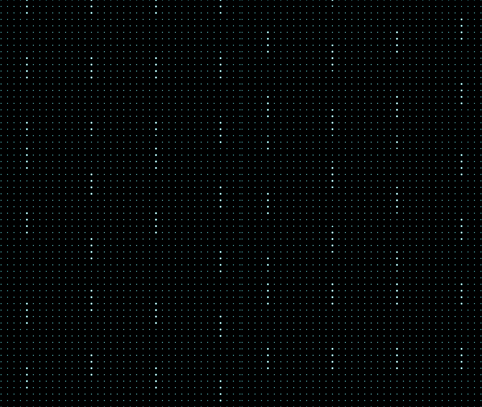
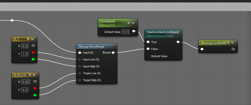
As you might guess, I do this in the same way I have done the earlier two
variations: create a random number for each column of tiles. In this case, the
random number will ultimately be in the range 0.05 - 0.6. This value is then
sent to the reroute node MovingLineSpeed. This speed value is used in
conjunction with the Time node (see the “Varying line start” section).
Combining the variations and dropping some of the background dots
Here’s how it all looks like when all of the variations are added together:
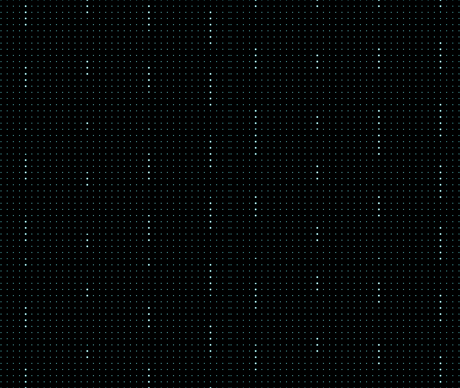
Does it not look nice? There is one more difference between this and the gif from the beginning of this post. We need to remove some of the background dots, the ones that are not moving, to get something that looks like this:
I do this in this material by using a pixelated version of LowResBlurredNoise,
a noise texture that is provided by Unreal:
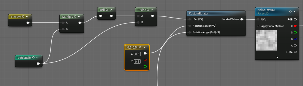
There are a few things going on here.
I am using the classic multiply -> ceil -> divide technique to pixelate the
noise texture. If you take the regular UVs given by the TexCoord node,
multiply it by some value n, do a ceil, and then divide it by n, you will
get a n x n window of pixelated UVsTechnically, I could have used
MF_UI_Pixelate and I would have gotten a similar result (though
MF_UI_Pixelate uses floor instead of ceil). I wrote this part of the
material a long time ago so I am leaving it alone.. But here, instead of using
the regular UVs, I am using this technique with tileduvs. This way, when I
feed the pixelated UVs into the noise texture, I ensure that I have one square
pixel of that noise for each dot in the material.
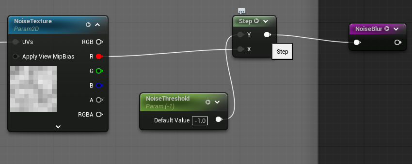
Now, I convert this pixelized texture into either a zero or a one using a
threshold via the Step node, which returns zero if the input (X) is less
than the threshold (Y) and one otherwise. In the following snippet, I send the
output to a NoiseBlur reroute node. I explain its use later. The threshold in
the screenshot is -1, effectively leaving all the background dots in the
material. The final version of the material shown in this blog has the threshold
set to 0.6.
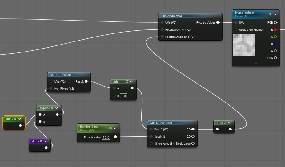
I also add a randomization step to ensure that removal of the background dots is not uniform across each tile. But before I explain this, let me explain about the UVs more.
When you pixelate the UVs, each square of the UV has exactly the same value. When they are fed to a texture, all the pixels that happen to lie within the same square of the UV will sample the same exact point of the texture. In other words, each square in the pixelated UVs will independently sample from the texture. Within each square, all of the pixels will sample the same point of the texture. Another thing to know is that you can rotate UVs. Although this is slightly difficult to conceptualize, rotating UVs means you change the points at which you sample the texture.
To perform the randomization, I rotate the pixelized UVs using a custom rotator.
Note that I am performing a random amount of rotation per tile. This is
intentional because then each DotDensity x DotDensity tile will have a
different set of removed background dots.
In my material, I combine the moving dots effect and the hiding of the background static dots. In particular, only static dots should be hidden. If there is a moving dot that happens to be in the same place as a hidden static dot, I want to show the moving dot.
To do this, I take the thresholded output (which was sent to the NoiseBlur
reroute node) and use it in conjunction with the moving mask (generated in) via
a Lerp node. If you now multiply the output of the Lerp with the output of
MF_UI_SDF_Circle, you will get the desired output. If the moving mask is 1,
then the currently computed position refers to a moving dots portion of the
material and we will always use the output of MF_UI_SDF_Circle. Otherwise, if
the moving mask is 0 for that currently computed position of the material, it
means the currently computed position refers to a static portion of the
material. In this case, we will rely on NoiseBlur. If NoiseBlur is 0, then
we will not show the circle and if NoiseBlur is 1, we will use the output of
MF_UI_SDF_Circle.
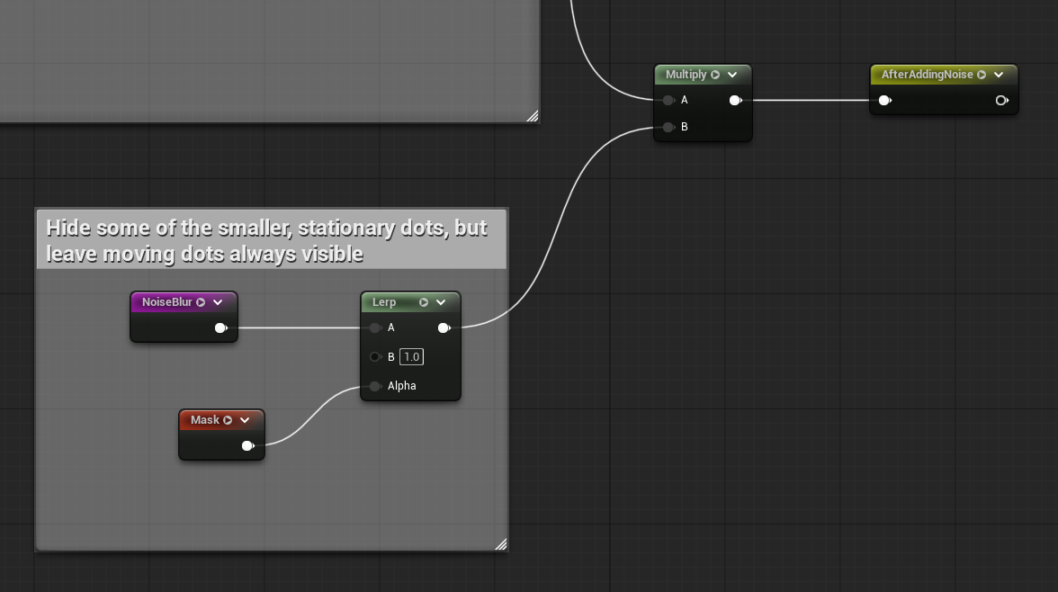
The combination of the moving dots and hidden dots is sent to the reroute node
AfterAddingNoise. You can now use this in the material output node with
different color values (and other material settings):
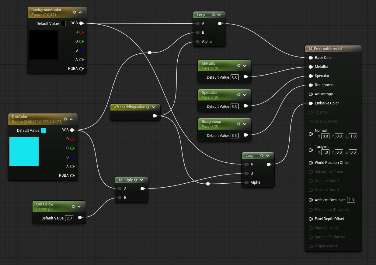
And that is how I construct the final material from the beginning of this post:
Cool, right? If you have any questions or comments, please feel free to contact me (my email address is in the About page).